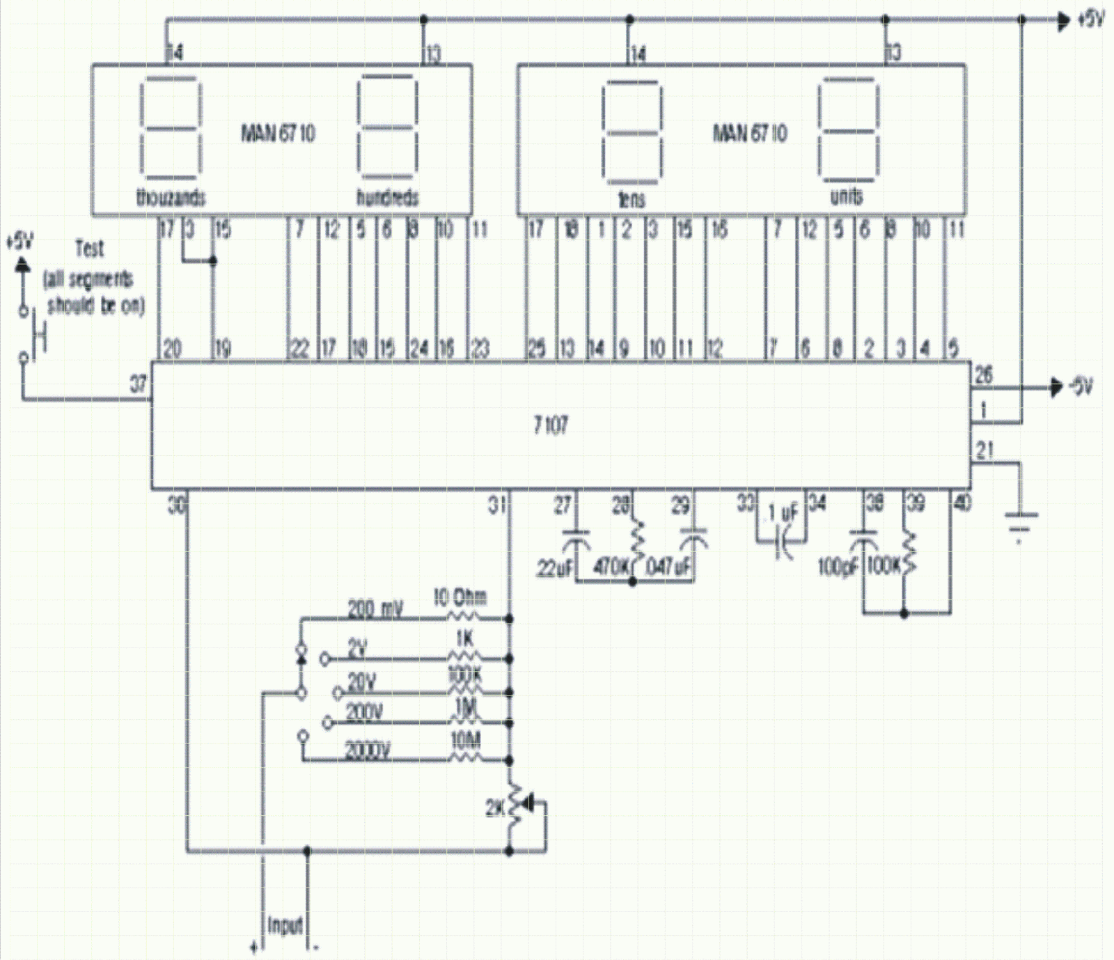
IC7107 is the most common and economic analog to digital converter available in market. It can convert an analog signal to 3 digit LED display.
The displays are seven segment LEDs (8). 7107 has a build in reference and a clock along with seven segment decoder and display driver.
The simple connectivity as per the circuit shall ensure a reliable A to D converter worth display. The power supply employed is +5V DC.
The input for this particular circuit could be any voltage up to 2000V. It is imperative to mention in this context that the highest displayable voltage is 1999V.
The input is being introduced between pin no. 30 & 31 through a parallel rung of resistors namely 10Ω, 1KΩ, 100KΩ, 1MΩ, 10MΩ for selection of ranges of 200mV, 2V, 20V, 200V and 2000V.
A push to on switch is connected between +5 V DC and pin no. 37 to check the health of all the segments of four displays.
The resistor used here are all quarter watt and the seven segment displays are common anode type.
It is advisable to download the data sheet of 7107 and use the recommended components.
The resistors need to be of 1% tolerance type for best result.


No comments:
Post a Comment