skip to main |
skip to sidebar
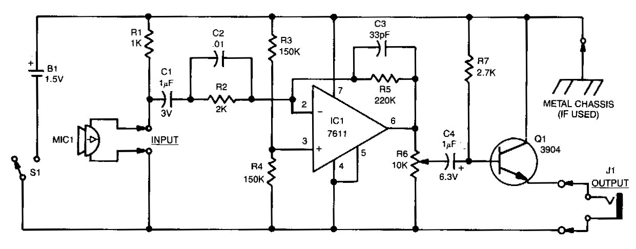
Micro Sized Amplifier Circuit Diagram
This is the simple Micro Sized Amplifier Circuit Diagram. This Micro Sized Amplifier Circuit Diagram Sound detected by electret microphone MIC1 is fed to IC1`s input through resistor R2, and capacitors Cl and C2. Resistors R2 and R5 determine the overall stage gain, while C2 partially determines the amplifier`s frequency response. To ensure proper operation, use a single-ended power supply. R3 and R4 simulate a null condition equalto half the power supply`s voltage at IC1`s noninverting input. The output of IC1 is transferred to emitter-follower amplifier Ql via volume control R6. The high-Z-in/low-Z-out characteristic of the emitter-follower matches the moderately high-impedance output of IC1 to a low-impedance headphone load.
Micro Sized Amplifier Circuit Diagram


No comments:
Post a Comment