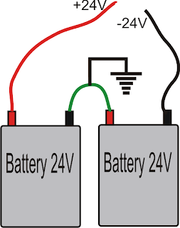
The circuit basically uses a push pull topology through a couple of 24V batteries. The use of two 24V batteries allows lower AH batteries to be incorporated with higher efficiency and wattage.
12V batteries can be also tried however the power output would be reduced to half.
Since a dual supply is used the connected transformer does not need to be a center tapped type, rather a two wire ordinary transformer becomes suitable here.
The couple of designs shown below are all that would be required for implementing this simple pure sine wave inverter circuit.
The first circuit is the basic sine wave generator which becomes the feeding input to the main sine wave amplifier or the output stage.
The sine wave generator produces a pure sine wave output with the shown components at about 50Hz, for other frequencies the 2.5K resistor may be altered, and tested in a simulator for fixing the desired results.
The sine generator circuit should be supplied with +/-12V, and not directly from the 24V battery supply as that might damage the IC permanently.
The opamps used in this sine generator are from the IC TL072
The next diagram shows the output stage of the proposed simple pure sine wave inverter circuit. As can be seen the design is not at all complicated.
All the involved components are standard, and easily available.
The mosfets are IRF540n and IRF9540n which compliment each other to produce the required push pull effect over the attached transformer.
With a 0-24V/25amp transformer, and a couple of 24V batteries the circuit would be able to generate as high as 600 watts of pure sine wave output at the relevant voltage.
The output across the right hand side opamp of the sine generator is to be connected across the input of the second circuit for initializing the proposed operations.
Battery Wiring Details for the above Simple Sine Wave Inverter Circuit


No comments:
Post a Comment