This is a Simple Signal Injector Circuit Diagram. The unit provides a square-wave output that is rich in harmonic content. The circuit`s output frequency can be varied from 50 Hz to 15 kHz. The heart of the circuit is a 555 a stable connected in its equal mark/space mode. The frequency is controlled by potentiometer R2 and capacitor Cl. Resistor R3 controls the output level with the output ac-coupled through C3.
This circuit uses a 555 timer that is setup to each run in associate A stable operative mode. This generates a nonstop output via Pin three within the type of a sq. wave. once the timer's output changes to a high state this triggers the a cycle the 4017 4017 decade counter telling it to output consecutive sequent output high. The outputs of the 4017 ar connected to the LEDs turning them on and off.
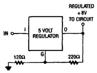
If you have trouble locating an 8-V regulator, although they are commonly available,a 5-V unit can replace it by connecting the regulator, as is shown here.
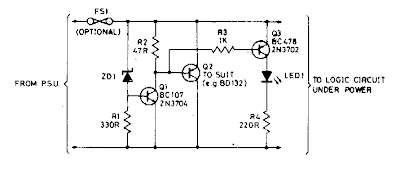
Zener diode ZD1 senses the supply, and should the supply rise above 6 V, Ql will turn on. In turn, Q2 conducts clamping the rail. Subsequent events depend on the source supply. It will either shut down, go into current limit or blow its supply fuse. None of these will damage the TTL chips. The rating of Q2 depends on the source supply, and whether it will be required to operate continuously in the event of failure. Its current rating has to be in excess of the source supply.
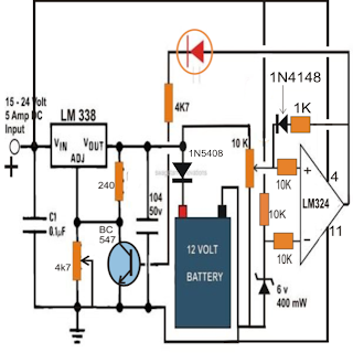
A simple yet accurate automatic, regulated 6/12/24 volt lead acid battery charger circuit is explained in this article. The circuit switches off the current to the battery as soon as the battery reaches full charge. An illuminated LED at the output indiacates the fully charged condition of the battery.
The circuit diagram may be understood from the following points:
Fundamentally the voltage control and regulation is done by the versatile, work horse IC LM 338.
An input DC supply volt in the range of 30 is applied to the input of the IC. The voltage may be derived from a transformer, bridge and capacitor network.
The value of the 47k preset is set to get the required output voltage, depending upon the battery voltage to be charged.
If a 6 volt battery needs to charged, R2 is selected to produce a voltage of around 7 volts at the output, for a 12 volt battery it becomes 14 volts and for a 24 volt battery, the setting is done at around 28 volts.
The above settings take care of the voltage that needs to be applied to the battery under charge, however the tripping voltage or the voltage at which the circuit should cut off is set by adjusting the 10 K pot or preset.
The 10K preset is associated with the circuit involving the IC LM324(1/4) which is basically configured as a comparator.
The inverting input of the IC 324 is clamped at a fixed reference voltage of 6 via a 10K resistor.
With reference to this voltage the tripping point is set via the 10 K preset connected across the non inverting input of the IC.
The output supply from the IC LM 338 goes to the battery positive for charging it. This voltage also acts as the sensing as well as the operating voltage for the IC 324.
As per the setting of the 10 K preset when the battery voltage during the charging process reaches or crosses the threshold, the output of the IC 324 goes high.
The voltage passes through the LED and reaches the base of the transistor which in turn conducts and switches off the IC LM 338.
The supply to the battery is immediately cut off.
However the moment voltage is switched OFF across the battery terminals, the battery voltage tends to fall rapidly to some lower value, normally this would trigger the op amp back into its original position and the power would be restored to the battery giving rise to a rapid switching of the output at the threshold levels. The introduction of the 470K resistor eliminates the above possibility and latches the system to a switch OFF position even with the fall in the battery voltage level....however this position is sustained only for some fixed lower level of the battery depending upon the value of the resistor (470k), increasing the value will make the difference less and vice versa.
(presently the 470K is replaced with a 1n4148/1K diode resistor, making the circuit a one-shot latch up device....so it won't respond to battery low level threshold, and will need to be manually reset in case the battery voltage falls below the lower threshold.)
The illuminated LED indicates the charged condition of the connected battery.
This automatic battery charger circuit can be used for charging all lead acid or SMF batteries having voltages in between 3 and 24 volts.