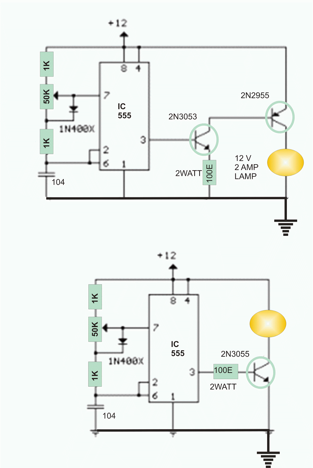
Lamp dimmer circuit is always a delight for the hobbyist. Here in this case, a 25W automobile lamp is being used as a dimmer element.
The lamp draws around 2 Amp of DC current. Hence for driving this bulb we need transistors those can handle such current.
In circuit 1 we have used primarily a PNP transistor 2N2955 to drive the bulb. This PNP is being biased by NPN transistor 2N3053, the base of which is triggered by a 555 timer.
The potential divider chain employed in conjunction with the 0.1 microFarrad capacitor produces a 200Hz square wave, the duty cycle of which can be varied by adjusting the 50K trimpot to an extent of 95% from 5%.
In circuit 2 the 2N3053 transistor is being omitted and instead of a PNP transistor a power transistor (2N3053) is being triggered by pin 3 directly.
A resistance of 100 ohms is being employed between pin 3 and base of the transistor. In case there is any gain oriented malfunction then a Darlington pair may have to be considered.


No comments:
Post a Comment